LuciadRIA supports the styling of feature data with the OpenGIS Symbology Encoding (SE) specification version 1.1.0
(OGC 05-077r4). It doesn’t support CoverageStyle encodings. This article gives an overview of the supported features with detailed information for each supported symbolizer
type.
Supported features
-
FeatureTypeStyle: describes the styling for a feature type. You can create aFeatureTypeStylewith multipleRules. -
Rules: stylingRulescontain one or more symbolizers, OGC Filters, and scale range limitations. The z-order increases for each consecutive rule and for each consecutive symbolizer inside the rule. -
Symbolizers: define the styling options for specific features, such as points, lines, polygons, or text. LuciadRIA ignores styling options that aren’t available in itsSEPainter. You can define OGC Filter expressions in a symbolizer where the OGC specification allows it. For example, you can use them to size icons that represent cities differently based on the number of city inhabitants. You can find more information about the supported features for each symbolizer in this article. -
uom: Unit-Of-Measure (UOM). The Symbology Encoding painter respects theuomunit-of-measure attribute in all symbolizers. It allows you to define the size of lines, icons, or text in meters or feet instead of pixels. In the absence of theuomattribute, the default unit-of-measure ispixels. See the individual symbolizer sections in this article to learn about possible limitations.
PointSymbolizer
In a PointSymbolizer, you use 'Graphic' elements to style point features. You can combine multiple Graphic elements in a single point symbolizer.
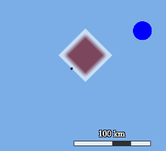
Check this code to create the preceding image:
<?xml version="1.0" encoding="UTF-8"?>
<FeatureTypeStyle version="1.1.0" xmlns="http://www.opengis.net/se">
  <Rule>
    <PointSymbolizer uom="http://www.opengeospatial.org/se/units/metre">
      <Graphic>
        <ExternalGraphic>
          <InlineContent encoding="base64">
            iVBORw0KGgoAAAANSUhEUgAAAAgAAAAICAYAAADED76LAAAAH0lEQVQYV2P8DwQMeAAjSEEdIyNWJU1AvUNHAT5vAgDR8jHptuzwOwAAAABJRU5ErkJggg==
          </InlineContent>
          <Format>image/png</Format>
        </ExternalGraphic>
        <Size>50000</Size>
        <Opacity>0.6</Opacity>
        <AnchorPoint>
          <AnchorPointX>0.75</AnchorPointX>
          <AnchorPointY>0.25</AnchorPointY>
        </AnchorPoint>
        <Rotation>45</Rotation>
      </Graphic>
      <Graphic>
        <Mark>
          <WellKnownName>circle</WellKnownName>
          <Fill>
            <SvgParameter name="fill">#0000ff</SvgParameter>
          </Fill>
        </Mark>
        <Size>25000</Size>
        <Displacement>
          <DisplacementX>75000</DisplacementX>
          <DisplacementY>50000</DisplacementY>
        </Displacement>
      </Graphic>
    </PointSymbolizer>
  </Rule>
</FeatureTypeStyle>
Graphic
You can define ExternalGraphic instances with OnlineResource and InlineContent elements. This corresponds to
the way you can paint icons with the drawIcon() method of the FeaturePainter.
It’s possible to map ExternalGraphic instances to icon images by specifying an IconProvider in the
SEPainterCreateOptions.
To learn how to use the IconProvider and the other ways to define ExternalGraphic instances, see
Map ExternalGraphics to distinct icon images.
LuciadRIA supports Mark with WellKnownName elements that contain well-known shape names. The allowed values include
square, circle, triangle, star, cross, x, pentagon and hexagon.
If you use an unrecognized name, the value is defaulted to square.
|
Although a |
All web formats that can be rendered on an HTML5 canvas are supported, including SVG graphics.
For InlineContent elements, LuciadRIA supports both base64 and XML encodings for SVG graphics. For other formats though, it supports only the
base64 encoding.
Graphic parameters
It’s possible to configure:
-
The
Size,RotationandOpacityof theGraphic. -
The
AnchorPointfor aGraphic. TheAnchorPointhas two valuesAnchorPointXandAnchorPointY. Both are numbers between 0 and 1, defaulting to 0.5, indicating which image position is anchored to the point styled with thisGraphic. -
The
Displacementfor aGraphic.Displacementhas two valuesDisplacementXandDisplacementY. Both are numbers indicating the offset of the image anchor compared to the point styled with thisGraphic.
LineSymbolizer
The Stroke parameter defines the general styling of the stroke of the line symbolizer.
Stroke
You can define a Stroke through a set of SVGParameters that shape the base stroke: stroke for the color, stroke-opacity, stroke-width, stroke-dasharray, stroke-dashoffset, stroke-linejoin, and stroke-linecap.
For the line join, LuciadRIA supports the values round, miter or bevel. For the line cap, it supports the values round, square, or butt.
In an SLD styling file for a line geometry, you can use the boolean SVG parameters marker-start and marker-end to place an arrow head respectively at the start point and end point of a line.
With this approach, you cannot customize the type of the arrow head itself; the style of the arrow head is based on the SLD
stroke properties defined in the encompassing LineSymbolizer.
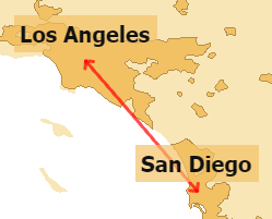
marker-start and marker-end.
Check this code to create the preceding image:
<?xml version='1.0' encoding='UTF-8'?>
<FeatureTypeStyle xmlns="http://www.opengis.net/se"
                  xmlns:xsi="http://www.w3.org/2001/XMLSchema-instance"
                  xsi:schemaLocation="
                   http://www.opengis.net/se
                   http://schemas.opengis.net/se/1.1.0/FeatureStyle.xsd"
                  version="1.1.0">
  <Description>
    <Title>San Diego To Los Angeles</Title>
  </Description>
  <Rule>
    <LineSymbolizer>
      <Stroke>
        <SvgParameter name="stroke">#ff0000</SvgParameter>
        <SvgParameter name="stroke-width">3</SvgParameter>
        <SvgParameter name="stroke-opacity">0.7</SvgParameter>
        <SvgParameter name="marker-start">true</SvgParameter>
        <SvgParameter name="marker-end">true</SvgParameter>
      </Stroke>
    </LineSymbolizer>
  </Rule>
</FeatureTypeStyle>|
If you do need to customize the arrow head type, you can place and rotate any |
GraphicStroke
You can combine the base stroke with a GraphicStroke. If the Graphic for this GraphicStroke has a user-defined AnchorPoint or a Displacement, LuciadRIA alters the position of the Graphic inside the stroke.
It’s possible to position graphics of the GraphicStroke inside gaps of a dashed base stroke through the InitialGap and Gap properties.
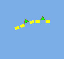
Check this code to create the preceding image:
<?xml version="1.0" encoding="UTF-8"?>
<FeatureTypeStyle version="1.1.0" xmlns="http://www.opengis.net/se">
  <Rule>
    <LineSymbolizer uom="http://www.opengeospatial.org/se/units/pixel">
      <Stroke>
        <SvgParameter name="stroke">#ffff00</SvgParameter>
        <SvgParameter name="stroke-width">10</SvgParameter>
        <SvgParameter name="stroke-dasharray">15 5 15 20</SvgParameter>
        <GraphicStroke>
          <Graphic>
            <Mark>
              <WellKnownName>triangle</WellKnownName>
              <Fill>
                <SvgParameter name="fill">#00ff00</SvgParameter>
              </Fill>
              <Stroke>
                <SvgParameter name="stroke">#ff0000</SvgParameter>
                <SvgParameter name="stroke-width">1</SvgParameter>
              </Stroke>
            </Mark>
            <Size>20</Size>
            <AnchorPoint>
              <AnchorPointX>0.5</AnchorPointX>
              <AnchorPointY>1</AnchorPointY>
            </AnchorPoint>
          </Graphic>
          <Gap>35</Gap>
          <InitialGap>35</InitialGap>
        </GraphicStroke>
      </Stroke>
    </LineSymbolizer>
  </Rule>
</FeatureTypeStyle>
GraphicFill
You can also define a Stroke through a GraphicFill. If you do so,
LuciadRIA ignores all other parameters. A GraphicFill can be used to create a stippled line.
|
Calculating the outline of the stroke that needs to get filled is computationally expensive. That’s why it isn’t updated in real-time if the zoom factor of the map changes. |
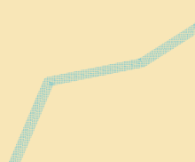
Check this code to create the preceding image:
<?xml version="1.0" encoding="UTF-8"?>
<FeatureTypeStyle version="1.1.0" xmlns="http://www.opengis.net/se">
  <Rule>
    <LineSymbolizer>
      <Stroke>
        <GraphicFill>
          <Graphic>
            <Mark>
              <WellKnownName>circle</WellKnownName>
              <Stroke>
                <SvgParameter name="stroke">#00000000</SvgParameter>
                <SvgParameter name="stroke-width">0.5</SvgParameter>
              </Stroke>
              <Fill>
                <SvgParameter name="fill">#17afe0</SvgParameter>
              </Fill>
            </Mark>
            <Size>1</Size>
          </Graphic>
        </GraphicFill>
        <SvgParameter name="stroke-width">20</SvgParameter>
      </Stroke>
    </LineSymbolizer>
  </Rule>
</FeatureTypeStyle>
PerpendicularOffset
You can define a PerpendicularOffset for a line symbolizer. You can use the offset to style a road with sidewalks, for instance.
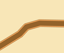
Check this code to create the preceding image:
<?xml version="1.0" encoding="UTF-8"?>
<FeatureTypeStyle version="1.1.0" xmlns="http://www.opengis.net/se">
  <Rule>
    <LineSymbolizer>
      <Stroke>
        <SvgParameter name="stroke">#93622a</SvgParameter>
        <SvgParameter name="stroke-width">50</SvgParameter>
        <SvgParameter name="stroke-linejoin">round</SvgParameter>
      </Stroke>
    </LineSymbolizer>
    <LineSymbolizer>
      <Stroke>
        <SvgParameter name="stroke">#ffaf64</SvgParameter>
        <SvgParameter name="stroke-width">5</SvgParameter>
        <SvgParameter name="stroke-linejoin">round</SvgParameter>
      </Stroke>
      <PerpendicularOffset>20</PerpendicularOffset>
    </LineSymbolizer>
    <LineSymbolizer>
      <Stroke>
        <SvgParameter name="stroke">#ffaf64</SvgParameter>
        <SvgParameter name="stroke-width">5</SvgParameter>
        <SvgParameter name="stroke-linejoin">round</SvgParameter>
      </Stroke>
      <PerpendicularOffset>-20</PerpendicularOffset>
    </LineSymbolizer>
  </Rule>
</FeatureTypeStyle>PolygonSymbolizer
You define the general styling of the stroke of the polygon symbolizer through the Stroke parameter.
All properties for Stroke inside the line symbolizer also apply here.
To define the general styling of the optional fill of the polygon symbolizer, use the Fill parameter.
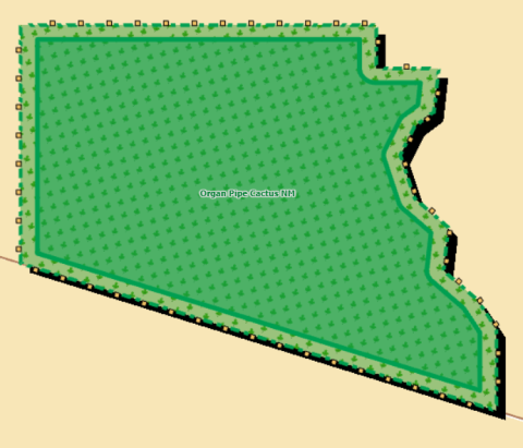
Check this code to create the preceding image:
<?xml version='1.0' encoding='UTF-8'?>
<FeatureTypeStyle xmlns="http://www.opengis.net/se"
                  xmlns:ogc="http://www.opengis.net/ogc"
                  xmlns:xlink="http://www.w3.org/1999/xlink"
                  xmlns:xsi="http://www.w3.org/2001/XMLSchema-instance"
                  xsi:schemaLocation="http://www.opengis.net/ogc
                  http://schemas.opengis.net/filter/1.1.0/filter.xsd
                  http://www.opengis.net/se
                  http://schemas.opengis.net/se/1.1.0/FeatureStyle.xsd
                  http://www.w3.org/1999/xlink
                  http://www.w3.org/1999/xlink.xsd"
                  version="1.1.0">
  <Description>
    <Title>Park areas</Title>
  </Description>
  <Rule>
    <MaxScaleDenominator>5.0E6</MaxScaleDenominator>
    <PolygonSymbolizer>
      <Fill>
        <SvgParameter name="fill">#000000</SvgParameter>
      </Fill>
      <Displacement>
        <DisplacementX>10</DisplacementX>
        <DisplacementY>-10</DisplacementY>
      </Displacement>
    </PolygonSymbolizer>
    <PolygonSymbolizer>
      <Fill>
        <GraphicFill>
          <Graphic>
            <ExternalGraphic>
              <OnlineResource xlink:href="/sampledata/img/leaf.png"/>
              <Format>image/png</Format>
            </ExternalGraphic>
            <Size>40</Size>
            <Rotation>345</Rotation>
          </Graphic>
        </GraphicFill>
      </Fill>
      <Stroke>
        <SvgParameter name="stroke">#009f51</SvgParameter>
        <SvgParameter name="stroke-width">4</SvgParameter>
        <SvgParameter name="stroke-dasharray">10 10 5 5</SvgParameter>
        <GraphicStroke>
          <Graphic>
            <Mark>
              <WellKnownName>square</WellKnownName>
              <Fill>
                <SvgParameter name="fill">#f2c164</SvgParameter>
              </Fill>
              <Stroke>
                <SvgParameter name="stroke">#000000</SvgParameter>
              </Stroke>
            </Mark>
            <Size>8</Size>
            <Rotation>0</Rotation>
            <AnchorPoint>
              <AnchorPointX>0.5</AnchorPointX>
              <AnchorPointY>0.75</AnchorPointY>
            </AnchorPoint>
          </Graphic>
          <Gap>22</Gap>
          <InitialGap>11</InitialGap>
        </GraphicStroke>
      </Stroke>
    </PolygonSymbolizer>
    <PolygonSymbolizer>
      <Fill>
        <SvgParameter name="fill">#009f51</SvgParameter>
        <SvgParameter name="fill-opacity">0.5</SvgParameter>
      </Fill>
      <Stroke>
        <SvgParameter name="stroke">#009f51</SvgParameter>
        <SvgParameter name="stroke-width">5</SvgParameter>
      </Stroke>
      <PerpendicularOffset>-15</PerpendicularOffset>
    </PolygonSymbolizer>
    <TextSymbolizer>
      <Label>
        <ogc:PropertyName>Unit_Name</ogc:PropertyName>
      </Label>
      <Font>
        <SvgParameter name="font-family">Tahoma</SvgParameter>
        <SvgParameter name="font-weight">bold</SvgParameter>
        <SvgParameter name="font-size">9</SvgParameter>
      </Font>
      <Halo>
        <Radius>1</Radius>
        <Fill>
          <SvgParameter name="fill">#dddddd</SvgParameter>
        </Fill>
      </Halo>
      <Fill>
        <SvgParameter name="fill">#007f31</SvgParameter>
      </Fill>
    </TextSymbolizer>
  </Rule>
</FeatureTypeStyle>
Fill
You can define a Fill through a set of SVGParameters that specify the color of a basic fill: fill for the color and fill-opacity.
GraphicFill
It’s also possible to define a Fill through a GraphicFill. If you do so, LuciadRIA ignores all other SVGParameters. You can use all possible graphics, including Mark, to create the fill pattern.
You can adjust the Size, Rotation and Opacity of the Graphic
used to create the pattern.
Adapting the AnchorPoint or the Displacement of a Graphic doesn’t influence the fill pattern created with that Graphic.
PerpendicularOffset
It’s possible to define a PerpendicularOffset for a polygon symbolizer.
|
Calculating the offset polygon is computationally expensive if the polygon symbolizer has a |
TextSymbolizer
In a TextSymbolizer, you use labels to style text features. Use label to specify the text content of the label.
LuciadRIA supports all Font parameters: family, style, size, and weight.
You can fill a text with a color of choice. The text can also have a halo with a certain radius. Although both the TextSymbolizer and the Halo have a Fill parameter, you can only use them for simple fills without GraphicFill.
labelPlacement
For labelPlacement, use either a PointPlacement to label features relative to the focus point of its Shape, or a LinePlacement to indicate that labels must follow the outline of the Shape.
-
PointPlacement: therotation,AnchorPointandDisplacementproperties are supported. -
LinePlacement:-
If you express the unit-of-measure in meters or feet, LuciadRIA forces the
isAlignedsetting totrue. -
If you set the
isRepeatedproperty totrue, LuciadIRA repeats the label along the path, taking into account the values for theGapandInitialGapproperties. -
The
generalizeLineproperty isn’t supported.
-
Vendor options
LuciadRIA supports the VendorOption named "conflictResolution" in TextSymbolizers. Setting this option to false disables decluttering for those labels. For example:
<TextSymbolizer>
    ...
   <VendorOption name="conflictResolution">false</VendorOption>
</TextSymbolizer>
If you disabled decluttering with the SEPainterCreateOptions, you can also use this flag to enable it again for specific TextSymbolizers.
|
Label decluttering only works for text that is actually added to the scene as a label. For world-sized text this is never
the case. When using |
LuciadRIA also supports label boxes in TextSymbolizers. To draw a box around a label, you make use of two vendor options named
"graphic-resize" and "graphic-margin".
For more information about label boxes, see How to draw a box around labels.
Unit-of-measure — UOM
It’s possible to define a unit-of-measure for your text symbolizer. LuciadRIA correctly interprets all size-related parameters, such as the height of your font, the radius of your halo, or the size of your label box.
|
For a TextSymbolizer with a unit-of-measure in meters or feet, LuciadRIA renders the text as bodies instead of labels. This
means that the text might appear underneath other layers. LuciadRIA also doesn’t reposition or declutter it. In addition,
it forces the |